Introduction
MSX is a computer standard that appeared in 1983 and was quite popular in some countries until approximately 1990. Despite not being used, games are still being developed by aficcionados.
This article aims to explain how graphics are represented in MSX1 memory and some techniques to save memory when writing a game.
Screen Modes
MSX1 supports some screen modes, each of them provides a specific resolution, number of colors and may or not support sprites.
| Screen Mode | Type | Colors | Sprites | Screen Number |
|---|---|---|---|---|
| Text 1 | 24 x 40 characters of 6 x 8 | 2 | None | 0 |
| Graphic 1 | 24 x 32 characters of 8 x 8 | 16 (2 per character) | Supported | 1 |
| Graphic 2 | 256 x 192 | 16 (2 each line of a tile) | Supported | 2 |
| Multicolor | 64 x 48 | 16 | Supported | 3 |
From those screen modes:
Text 1is only for text and does not support spritesGraphic 2consumes memory and it is slower since it is pixel-basedMulticolorhas a very low resolution for a decent game (what is the use of this screen mode ?)
When I had my MSX1, I had the impression that Graphic 2 would be the only go-to screen mode for games.
Although games are also built with it, I was surprised to know many years after that Graphic 1 was actually much more popular due to its speed to print custom characters, support for some character color as well as support for sprites.
Another interesting fact is that displaying graphics in MSX1 under Graphic 1 is about settig values to specific addresses in MSX1 video memory (VRAM).
Keep in mind that VRAM is a separate memory from RAM which is accessed directly by the microprocessor. VRAM is the graphics card memory and stores graphics definitions, due to that, values need to be copied from RAM to VRAM. More details on that later.
By setting values to VRAM memory addresses one can redefine character patterns and colors, display characters on screen, define and display sprites.
Graphic 1 Settings
Each graphic mode also
Graphic 1 Memory Structure
VRAM memory is divided in sections that store information on different graphic aspects.
Given Graphic 1 mode is active for 16x16 sprite size, the memory table can be represented as:
| Title | Start | End | Size (bytes) | Comments |
|---|---|---|---|---|
| pattern generator table | 0x0000 | 0x07FF | 2048 | pattern generator table |
| pattern name table | 0x1800 | 0x1AFF | 768 | 24 rows x 32 cols of char |
| sprite attributes table | 0x1B00 | 0x1B7F | 128 | 32 sprites with 4 bytes each |
| pattern color table | 0x2000 | 0x201F | 32 | pattern block colour |
| palette table | 0x2020 | 0x204F | 48 | what is this ??????? |
| sprite generator table | 0x3800 | 0x3FFF | 2048 | 32 sprite 16x16 |
ref: https://konamiman.github.io/MSX2-Technical-Handbook/md/Appendix5.html#screen-1–graphic-1
Pattern Generator Table
The pattern generator table is where the display of ASCII symbols are defined.
For instance, the letter A is identified by the ASCII code 0x41 but its visual pattern is described between the addresses 0x0208 and 0x020F in the pattern generator table as:
| 1 | 2 | 3 | 4 | 5 | 6 | 7 | 8 | mem address | hex value |
|---|---|---|---|---|---|---|---|---|---|
| X | 0x0208 | 0x20 | |||||||
| X | X | 0x0209 | 0x50 | ||||||
| X | X | 0x020A | 0x88 | ||||||
| X | X | 0x020B | 0x88 | ||||||
| X | X | X | X | X | 0x020C | 0xF8 | |||
| X | X | 0x020D | 0x88 | ||||||
| X | X | 0x020E | 0x88 | ||||||
| 0x020F | 0x00 |
The memory address range for “A” as shown above can be calculated via the following:
- memory_start = ASCII code * 8 = 0x41 * 8 = 0x0208
- memory_end = ASCII code * 8 + 8 = 0x41 * 8 + 7 = 0x020F
With these formulas in mind, the address range for the remaining font symbols can be calculated given the ASCII code table below:
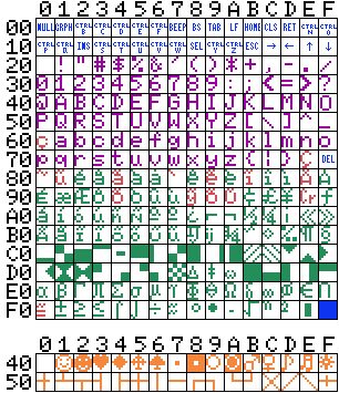
However only some parts of the tile map memory can actually be used to redefine symbols for a game since some of the ASCII code actually works for control and do not correspond to visible symbols.
Other symbols are uppercase letters and number without which text messages can’t be displayed on the game.
| \ | 0 | 1 | 2 | 3 | 4 | 5 | 6 | 7 | 8 | 9 | A | B | C | D | E | F |
|---|---|---|---|---|---|---|---|---|---|---|---|---|---|---|---|---|
| 00 | C | O | N | T | R | O | L | C | H | A | R | S | ||||
| 10 | C | O | N | T | R | O | L | C | H | A | R | S | ||||
| 20 | SPC | |||||||||||||||
| 30 | 0 | 1 | 2 | 3 | 4 | 5 | 6 | 7 | 8 | 9 | : | ; | < | = | > | ? |
| 40 | @ | A | B | C | D | E | F | G | H | I | J | K | L | M | N | O |
| 50 | P | Q | R | S | T | U | V | W | X | Y | Z | [ | \ | ] | ^ | _ |
| 60 | ||||||||||||||||
| 70 | DEL | |||||||||||||||
| 80 | ||||||||||||||||
| 90 | ||||||||||||||||
| A0 | ||||||||||||||||
| B0 | ||||||||||||||||
| C0 | ||||||||||||||||
| D0 | ||||||||||||||||
| E0 | ||||||||||||||||
| F0 | cursor |
This leaves the following ranges available for redefinition:
- 0x21 - 0x2F (excluding 0x20 for “space” symbol)
- 0x60 - 0x6F
- 0x70 - 0x7E (excluding 0x7F corresponds for “delete” command)
- 0x80 - 0x8F
- 0x90 - 0x9F
- 0xA0 - 0xAF
- 0xB0 - 0xBF
- 0xC0 - 0xCF
- 0xD0 - 0xDF
- 0xE0 - 0xEF
- 0xF0 - 0xFF
Pattern Color Table
Every block of 8 characters can have its foreground and background redefined.
This is defined by a sequence of only 32 bytes where each byte encodes both the foreground and background colors.
The most signicative part is for the foreground color while the least significative for background color.
Ex: the byte 0x06FF encodes 0x06 (red) for foreground color and 0xFF (white) for background color.
Table below shows which ASCII code range is affected by each pattern table memory address.
| ASCII range | mem address |
|---|---|
| 0x00 to 0x08 | 0x2000 |
| 0x09 to 0x0F | 0x2001 |
| 0x10 to 0x18 | 0x2002 |
| 0x19 to 0x1F | 0x2003 |
| …. | …. |
| 0xF9 to 0xFF | 0x201F |
Pattern Name Table
While the pattern generator table defines the symbols patterns, the pattern name table is about displaying such symbols.
The table in this case represents screen area represent by the 32 columns and 24 rows of Graphic 1.
| \ | 0x00 | 0x01 | 0x0 | 0x03 | … | 0x1F |
|---|---|---|---|---|---|---|
| 0x1800 | (0,0) | (0,1) | (0,2) | (0,3) | … | (0,31) |
| 0x1820 | (1,0) | (1,1) | (1,2) | (1,3) | … | (1,31) |
| 0x1840 | (2,0) | (2,1) | (2,2) | (2,3) | … | (2,31) |
| 0x1860 | (3,0) | (3,1) | (3,2) | (3,3) | … | (3,31) |
| … | … | … | … | … | … | … |
| 0x1AE0 | (23,0) | (23,1) | (23,2) | (23,3) | … | (23,31) |
This way setting the value 0x41 to memory address 0x1800 will display symbol that corresponds to ‘A’ to be displayed in the top left corner of the screen.
Filling a screen with characters consumes 768 bytes which corresponds to 32 cols * 24 rows.
Given the limited memory space for MSX1, a better aproach to display tiles (chars) is needed to save memory for multiple game stages and other aspects.
Consider referring multiple blocks instead of single characters
Instead of addressing 1 character at a time, a block could represent multiple characters at once. This abstraction should be created at the code level.
For instance a line of 24 characters could be represented by 1 logical block when displaying the screen. Something like a function BRICK(10,10,5) where (10,10) is the start location of the block and 5 is the number of time the symbol chosen to represent a brick (for instance) would repeat in a horizontal sequence.
Another abstraction example is for displaying the clouds, if you need to reproduce the symbols patterns, another function let’s say CLOUD(2,2) could be responsible for drawing the clouds starting on the designated position (2,2). Therefore the CLOUD function could represent something like 5 to 6 individual characters.
Keep in mind that the location information as (row, col) could be represented with 1 byte to make the block representation in memory more compact.
Sprites
Sprite patterns are defined in the sprites generator table while their attributes such as precedence, (X,Y) location on the screen and color will be found in the sprite attributes table.
Sprite Generator Table
With Graphic 1 and large sprite mode enabled (16x16 pixels), 64 sprites of 16x16 pixels can be defined with 32 bytes each.
Sprite patterns are defined the following way in VRAM memory:
| sprite id | memory start | memory end | byte size |
|---|---|---|---|
| 0 | 0x3800 | 0x381F | 32 |
| 1 | 0x3820 | 0x383F | 32 |
| 2 | 0x3840 | 0x385F | 32 |
| … | … | … | 32 |
| 63 | 0x3FE0 | 0x3FFF | 32 |
Each 8 bytes group define the patterns of different section in the following order:
- top-left
- bottom-left
- top-right
- bottom-right
Sprite Attributes Table
Once sprite patterns are defined, in order to display them on the screen, attributes need to be used.
Each sprite attribute row in memory contains 4 attribute wuth 1 byte each in the following order (4 bytes total):
- Y
- X
- pattern number
- color (4 least significtive bits)
PS: The sprite precedence is defined by the row position on the table. The first row (4 bytes) is for the “top” sprite, then 1st row for the next precedence and so on until last position (31) is for the “bottom” sprite.
Sprite attribute table per sprite is:
| sprite id | memory addr |
|---|---|
| 0 | 0x1B00 |
| 1 | 0x1B04 |
| 2 | 0x1B08 |
| 3 | 0x1B0D |
| … | … |
| 31 | 0x1B7C |
Conclusions
Using Graphic 1 in MSX1 (and other graphic modes too) is mostly about setting values to VRAM memory tables. Once you know how to use those tables it is possible to refedefine ASCII fonts to be later used to display the game stage scenes in an efficient manner than trying to draw pixel by pixel.
Also with such tables, sprites patterns and attributes can be set.
However when displaying characters on the screen, there is a real opportunity to save memory space by moving from trying to fill the entire screen of 32x24 characters with 1 character at a time and occupy 768 bytes to using functions to displat blocks of characters in a programatic manner and thus providing a memory saver approch to the limited memory size of MSX1.